| Overview |
|
| |
History:
Electronic
Musical Instruments
Classification by sub-system technology:
"Analog":
Completely analog signal processing with control voltages (CV),
in polyphonic machines each channel is implemented as a separate
monophonic synthesizer, VCO with square/sawtooth/triangle/sine/variable
pulse waveform generation with CV for frequency and waveform shape,
VCO optionally has a sync input (normally triggered via output of
other VCO), analog multipliers (e.g. ring-modulator) for waveform
mixing, analog noise generator with filter for spectral shaping,
VCA for volume envelope shaping, VCF with resonance for "subtractive"
spectral shaping
a)
analog CV generation and processing by use of analog envelope generators,
analog LFO (LF VCO) for modulation, analog random-CV generators
based on noise generators with sample&hold (S&H) techniques.
Sequencers mostly based on SSI TTL or CMOS counters+demultiplexers
and analog CV gates.
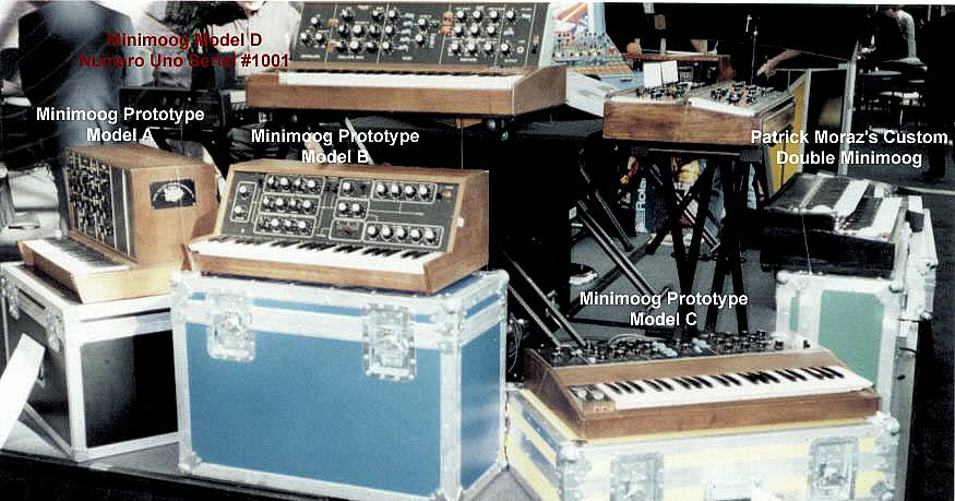
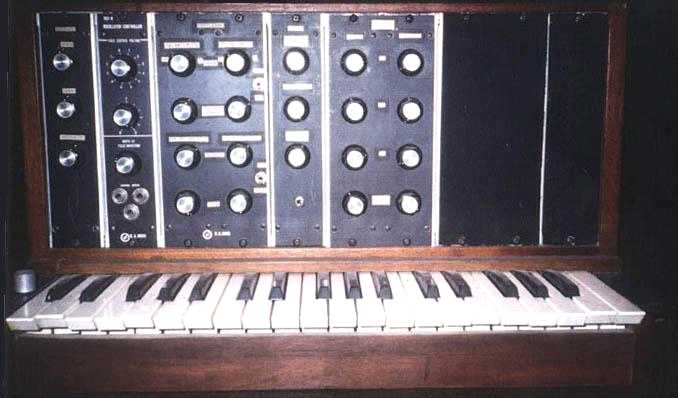
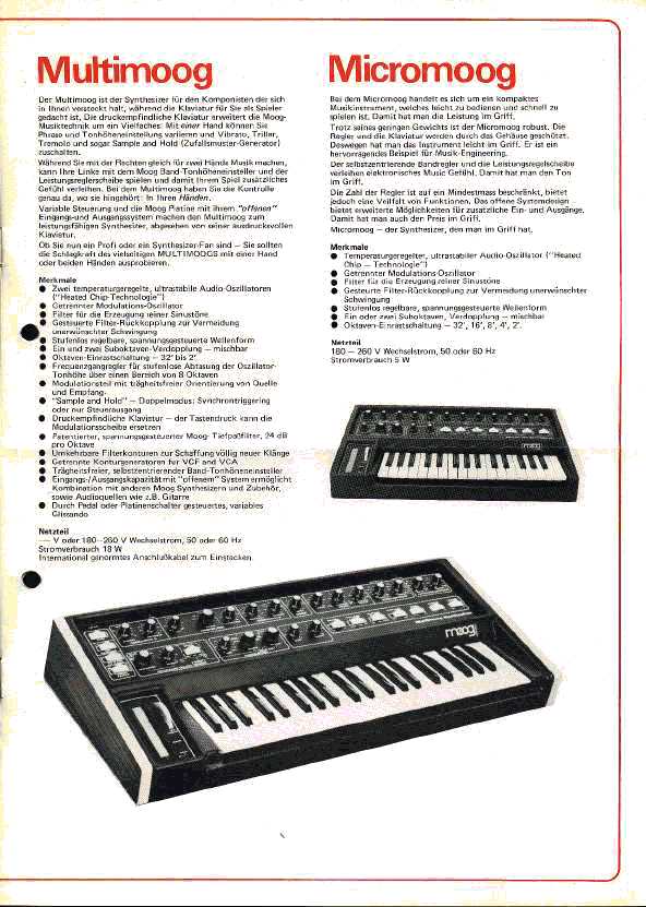
Example: Moog Modular, MiniMoog, PPG Model 300, PPG 1002, Korg PS-3100,
most early modular monophonic/polyphonic analog synthesizers and
drum machines
b) "Hybrid analog": digital control
subsystem, partially even digital envelope generators and LFOs,
DACs for CV generation, typically "programmable" polyphonic
with digitally storable sound patches and settings. Later models
often use digitally controlled oscillators (DCO, e.g. Xtal master
with frequency dividers) with analog waveform generation. Microprocessor-based
sequencers.
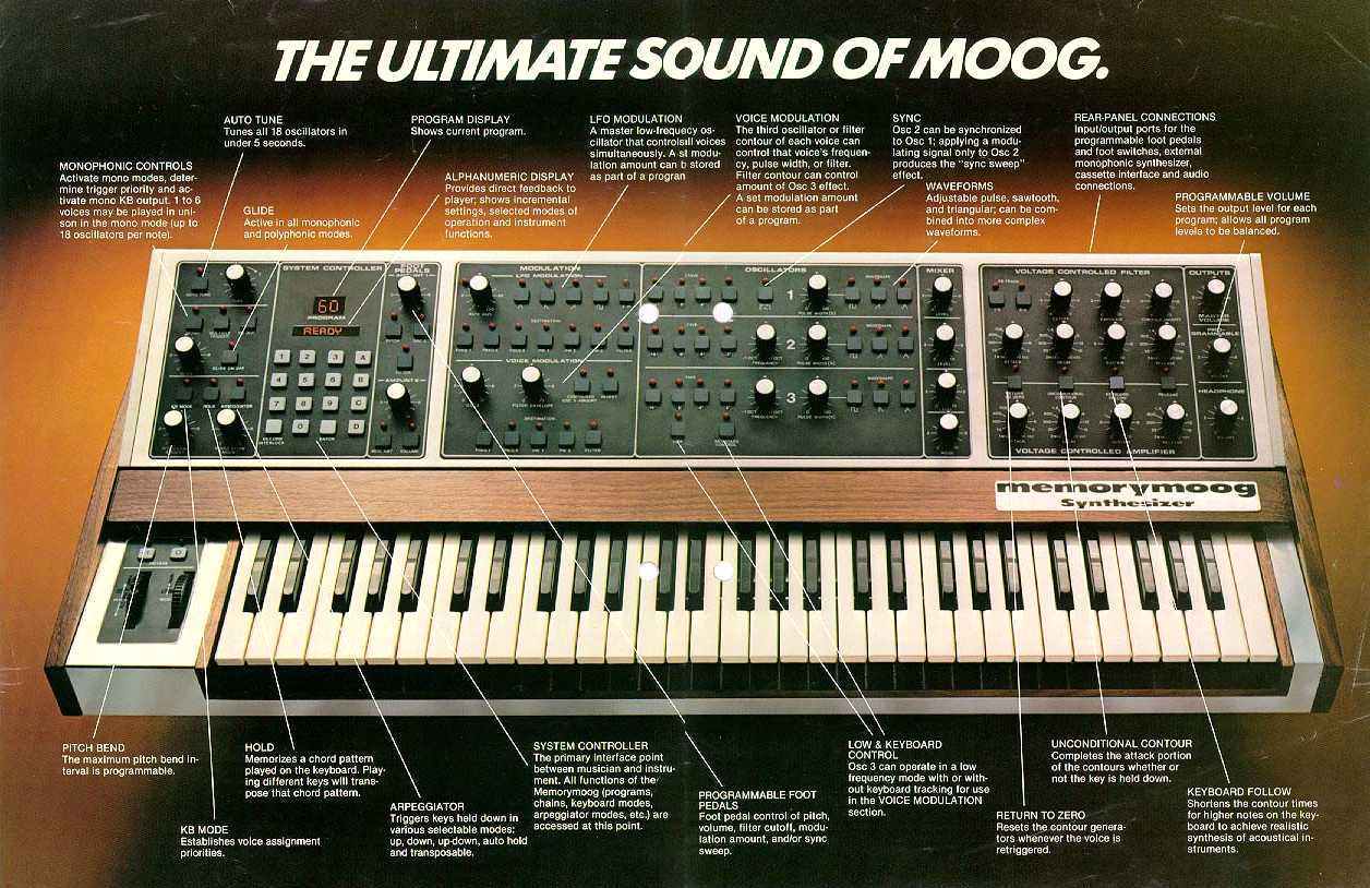
Example: PPG 1003, Yamaha CS80, MultiMoog, MemoryMoog, Jupiter-8,
Juno series, Prophet-5, TB303, CR78, TR808, TR909 (partially), most
MIDI-era analog synthesizers and drum machines
"Digital":
Digital control, digital envelope generators, digital waveform generation,
digital or analog (VCO) clock generators, microprocessor control
1) variable clock frequency for pitch variation per
channel, each channel has a separate clock generator (or even VCO)
as waveform data clock, separate waveform output DACs with analog
post-processing VCA (or MDAC) and VCF for envelope and spectral
shaping.
1a) wavetable synthesizer/sampler: clock advances
sample address register by one.
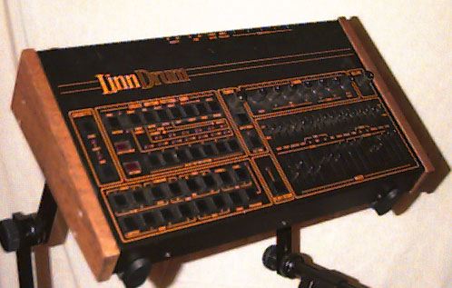
Example: Fairlight CMI, PPG Wave 2, Emulator II, Emulator III, Drumulator, LinnDrum,
TR909 (partially), early digital wavetable synthesizers/samplers
and drum machines
1b) special FM synthesizer: clock triggers phase register
increment, phase and phase increments are variable but fractional
(i.e., 0<=phi<2*pi), digital phase/frequency modulation via
sine lookup-tables and phase adders.
Example: Synclavier (digital FM synthesizer)
2) pitch variation by variable phase increment at
fixed clock rate, phase accumulator has integer and fractional part
(or even floating-point), decimation/interpolation algorithm to
obtain sample value from phase accumulator, fixed waveform data
output rate with parallel or time-multiplexed processing of multiple
channels.
2a) Shared or separate DACs, envelope and spectral
shaping by analog VCF/VCA post-processing, in modern designs waveform
generation often implemented by use of ASICs.
Example: PPG Wave 2.2, Ensoniq Mirage, Ensoniq ESQ-1, Waldorf Microwave,
early digital wavetable synthesizers/samplers and drum machines
2b) Completely digital signal processing, digital
envelope-shapers and filters, typically digital effect machines
included with multiple digital audio-busses (e.g. I2S), typically
mixed multi-channel digital and analog outputs, typically implemented
by ASICs and CPUs/DSPs.
Example: Yamaha GS1, DX7, Kawai K5, Emulator IIIX, most modern samplers,
wavetable or algorithmic (e.g., additive, FM, virtual analog, acoustic
modeling, granular synthesis) synthesizers and drum machines
Notes:
- The
main classification of "Analog" and "Digital"
is based on the waveform generation.
- VCO/VCF/VCA
with digitally generated CVs (via DAC) are sometimes called DCO/DCF/DCA.
Quite often the term DCO is also used for a digital clock generator
(e.g. based on bit-rate-multipliers ("BRM") and dividers).
- Analog-a)
could also be considered as a special-purpose analog computer
for sound generation.
- Analog-a)
and Analog-b) differ in system/envelope control.
- The
exotic case Digital-1b) could also be considered as a combination
of Digital-1) and Digital-2a).
- Digital-2a)
and Digital-2b) differ in post-processing.
- Digital-2b)
could also be considered as a special-purpose computer for sound
generation, without the historically grown separation into logical
units/sub-systems like oscillator, waveform generator, envelope
generator and post-processing. Even the classical algorithms like
additive, wave-table or FM/PM can be seen as compromises in older
generations of digital synthesizers due to technical limitations.
- The
table above lists extreme categories, combinations are possible.
- Early
samplers and wavetable synthesizers with limited Bit-counts and/or
sample-memory have used non-linear encoding/companding schemes
of sample-values (e.g. 8-Bit mu-255 and/or DPCM) to improve the
signal-to-noise ratio as compared to linear encoding. Examples:
LinnDrum, Emulator.
Frequency-
and phase-modulation synthesis:
Given are 2*pi-periodic functions a1(phi1) and a2(phi2) with time-dependent
phases phi1=phi10+omega1*t and phi2=phi20+omega2*t, respectively.
(Note that omega=2*pi*f). Frequency-modulation (FM) and phase-modulation
(PM) are defined as:
- Phase-modulation
(PM) is defined as:
a12(t)=a1(phi10+omega1*t+phi12*a2(phi20+omega2*t))
with the so-called modulation-index phi12.
- Frequency-modulation
(FM) is defined as:
a12(t)=a1(phi10+omega1*t+(omega12/omega2)*A2(phi20+omega2*t))
with A2 such that a2=dA2/dphi and the frequency deviation omega12.
The modulation-index thus is omega12/omega2, which is frequency-dependent.
Note that the "momentary frequency of a1" thus reads
dphi1/dt=omega1+omega12*a2 (hence "frequency modulation").
Note
that the modulation-index determines the Fourier-spectrum of the
resulting function a12. (In general, FM and PM are only equivalent
if a1 and a2 are special functions such as sine or cosine). If the
ratio of omega1 and omega2 is irrational (i.e. the frequencies are
in-commensurable), the spectrum of a12 becomes non-harmonic (i.e.
a12 is not periodic).
"FM synthesis" is very often implemented as a phase-modulation.
PM has the advantage of a frequency-independent modulation index
(which determines the spectrum and hence the "sound" or
"timbre") and a DC-free output (which is especially important
in higher order modulation chains to avoid detuning.) In general,
multiple oscillators with variable amplitudes, phases and frequencies
can be employed, especially complex modulation chains, where an
oscillator output is employed as a modulation source for other oscillators.
(Concerning the amplitude modulation, additive synthesizer concepts
are closely related, see below.)
For technical reasons (stability + modulation-speed and -depth),
almost all FM/PM syntesizers have a digital oscillator/modulator
implementation (phase accumulator registers, multipliers, adders,
waveform ROMs, see e.g. Yamaha GS1 or DX7). One of the strengths
of FM/PM synthesis is the ability to easily produce complex (esp.
non-harmonic) spectra (in contrast to subtractive synthesis and
classical additive synthesis, see below) and the broad range for
real-time timbre control/modulation. Using non-sine functions further
enhances the possibilities of FM/PM synthesis (e.g. a combination
of FM and wavetable synthesis as used in the FM-part of the Synclavier
and later Yamaha synthesizers).
Historically, John Chowning of Stanford University has invented
(and patended later on) the concept of using FM for audio signal
synthesis.
(Note: Typically, classical FM/PM synthesis can produce "bell-like"
and "metallic" sounds. FM/PM sound-programming, esp. trying
to reproduce realistic sounds, is complicated and not straight-forward
from scratch, although interesting artificial timbres can be obtained
quite easily.)
Fourier,
additive, and wavetable synthesis:
Let us first consider a given audio signal, which is nothing but
a time-dependent real function a(t). In a digital synthesizer, the
audio signal is sampled at equally spaced discrete points in time,
and the sample-values are discretized, i.e. quantized (but not necessarily
linearly, e.g. mu-law companded).
The so-called Fourier transformation provides a complex frequency-dependent
function A(f) (the "spectrum") for such a given time-dependent
audio sample. Firstly, we have to note that the values of a Fourier-transformed
function are complex, i.e. they have a phase and amplitude. Furthermore,
restricting the audio sample to discrete time-values with step width
dt, the resulting spectrum becomes highly symmetric (A(f)=A(f+n*fmax)
with fmax=1/dt and an integer n). (We assume that the original a(t)
is bandwidth-limited to -fmax/2,...,fmax/2 in order to avoid aliasing.
Then, the original a(t) can be fully restored via "sin(x)/x
folding" according to the sampling theorem.). The assumption
of a real sample function a(t) implies that A(-f)=A*(f) (i.e. complex
conjugated). It is therefore sufficient to restrict ourselves to
the interval f=0,...,fmax/2 (e.g. with dt=10microsec => f=0...50kHz).
The next important property of the spectrum lies in the fact that
the sample function a(t) has a finite length, i.e. t=0...tmax. Thinking
of a periodic continuation (period tmax), the frequency spectrum
also becomes discrete in the frequency-variable (providing a so-called
Fourier-series) in steps df=1/tmax (e.g. tmax=10sec => df=0.1Hz).
Hence we have Nt=tmax/dt time values and Nf=fmax/df frequency value,
giving Nf=Nt/2. Note that the factor of 2 basically stems from the
fact that the spectrum A(f) is complex-valued (real and imaginary
part or: amplitude and phase), whereas a(t) is real, giving the
same amount of information. The Fourier transformation of such periodic
discrete-argument functions is called discrete Fourier transformation
(DFT). As a special case, if Nt is a power of two (i.e. Nt=2^n with
some integer n), the DFT can be computed very efficiently by use
of the fast Fourier transform algorithm (FFT).
The periodic continuation of an audio sample (we have introduced
above as a simplifying assumption) can be re-interpreted in the
case of a very small tmax: If df=1/tmax lies in the audio range
(e.g. tmax=1msec => df=1kHz), tmax becomes nothing but the so-called
base-period of a stationary sound-wave. In this case, df is nothing
but the base-frequency. Furthermore, since we have seen that f can
only take discrete values, namely an integer times df, the spectrum
of such a sound has an evenly-spaced comb-structure which is called
harmonic.
So far, we have considered the purely time-dependent audio sample
a(t) and its purely frequency-dependent spectrum A(f). Where a(t)
is the object that samplers deal with, the A(f) for a large tmax
(e.g. 10sec) is often not very useful in terms of synthesizers.
One has to note that the human ear perceives something like a combined
time- and frequency-dependent function: Roughly spoken, everthing
above approx. 20msec is time-resolved. That is, the complete Fourier
transformation as discussed above is not the mathematical method
we are looking for. From this point we can take various paths for
contructing an algorithm which is adequate for the ear's analyzing
capabilities. Here, we want to discuss two synthesizer concepts:
- The
so-called short-time discrete Fourier transformation (STDFT) as
used in
digital additive and wavetable synthesizers, as well as in effect
engines. Here, the whole sample (the time-dependent function a(t))
is split into smaller, possibly overlapping "time-frames"
of equal sizes (typically tmax(frame)<<20msec see above)
giving b(t1,t2):=a(t1+t2) with two time-variables: time within
frame t1 and frame start position t2. At this point, the STDFT
analysis makes a partial DFT (or FFT see above) within each frame,
providing a time- and frequency-dependent function B(f1,t2) (time-dependent
"frequency frames" or "timbres"), in contrast
to a complete Fourier analysis of the whole sample, which provides
a purely frequency-dependent function.
Non-harmonic spectra, broadened peak-structures, and sub-harmonics
can be generated (to a certain degree) by choosing synthesis/analysis
frames with a length given by an integer multiple of the audible
base-period (e.g. an FFT frame of 2048 samples for a base-period
of 128 samples). To avoid audible sub-harmonic artefacts (given
by the time-frame length), overlapping frames are typically used.
The
STDFT is employed to resynthesize (from samples) or create sounds
in a time-frequency domain, which is related to the human ear's
sound-reception properties. After creating/editing this fuction
B(f1,t2), the STDFT synthesis generates b(t1,t2) which in turn
is played back by the wave-table sound generator. Here, the index
t1 is looped continuously and t2 is slowly varied according to
a given envelope generator ("small-loop sample-player with
varying loop position"). In that sense, samplers (which play
a(t)) can be considered as wavetable synthesizers which play each
frame in b(t1,t2) only once (yielding the time-scaling "artefact"
with varying pitch which is typical for samplers).
As a generalization, the playback-speed/phase within the frame
(t1) can be modulated, providing an additional frequency/phase
modulation of the varying frame-waveform (see FM/PM synthesizers
above, e.g. FM-part of Synclavier).
-
Additive synthesis. Here,
we start from a small tmax (<<20msec see above) for just
one base-period of a stationary sound-wave a1(t), characterized
by its spectrum A1(f). The concept of an additive synthesizer
is to vary the individual amplitudes (and possibly phases) in
A1(f) (normally slowly) in time during playback. (Please note
that a stationary sound-wave is perceived by the human's ear as
a sine-like tone after some time.) Mathematically, we hence introduce
a function B1(f,t) (with B1(f,0):=A1(f)) which is is employed
by the sound generator ("set of equi-distant sine-oscillators
with individual envelopes") to compute an output signal in
real-time.
As a generalization, we can discard the condition of evenly-spaced
oscillator frequencies and additionally vary each oscillator's
frequency in time, providing frequencies f(i,t) (with i the oscillator
index) and generalized envelopes E(i,t). Please note that we already
produce a non-harmonic generator output (if long-time Fourier-analyzed)
if B1(f,t) above varies in time: The phase variation provides
a frequency shift of the individual oscillator (proportional to
dphi/dt) and the amplitude variation broadens the peaks (proportional
to d|B1|/dt, formerly delta-functions). Such a concept of a set
of sine-oscillators with time-dependent amplitudes, phases and
frequencies is nothing but an FM/PM synthesizer (especially if
oscillator outputs serve as modulation sources for others, see
FM/PM above). At this point, we speak of a classical additive
synthesizer if we have oscillators with fixed evenly-spaced frequencies,
and of a classical FM/PM design if sine-oscillators with variable
frequencies/phases and amplitudes are employed.
One
has to note a similarity between the B(f1,t2) of the wave-table
synthesizer and the B1(f,t) of the real-time additive synthesizer.
(Hence, wave-table techniques are sometimes also referred to as
additive.) These two synthesizer concepts are mathematically equivalent
under special conditions, the sound quality of such machines is
closely related. Due
to the large number of required oscillators in the concept of real-time
additive synthesis (as defined above), historically, samplers and
wavetable techniques in conjunction with non-realtime waveform generation
software have been used (e.g. Fairlight CMI or PPG Wave). For technical
reasons (oscillator stability), most additive and wave-table synthesizers
employ digital implementations. Modern additive synthesizers are
based on DSPs (e.g. Kawai K5000).
(Note: Typically, classical additive/wavetable synthesis can produce
"technical", "organ-like" and "bright"
sounds. Additive/wavetable sound-programming, esp. trying to reproduce
realistic sounds, is tedious. Programming from scratch often results
in stationary and primitive timbres. However, with the help of the
resynthesis of recorded samples it becomes quite intuitive and provides
interesting "surrealistic" timbres.)
Digital
pitch generation overview:
Typically, two different approaches have been pursued in digital
synthesizers
and samplers to vary the pitch (see above):
1) variable clock rate:
advance one original sample (in sampler/wavetable synthesizer, one
phase step in Synclavier FM synthesizer) per clock pulse. This requires
a programmable digital oscillator/bit-rate-multiplier/divider (or
even a VCO) and a DAC for each output channel. Typically, a VCF/alias
tracking filter and VCA is used for analog post-processing. Used
in older (small series, custom design, expensive) wavetable synthesizers
and samplers, also in older drum machines with a VCO as clock generator.
With a perfect sample clock, the quantization and alias noise has
always the same relative spectrum, independent of pitch because
ratio "playback pitch : sample-output rate" is constant.
Hence, such a pitch generation scheme is generally considered to
provide a high quality natural sound from a musical point of view.
However, typical digital oscillator implementations (based on bit-rate-multipliers
and/or dividers) often have slight phase fluctuations (jitter) producing
additional noise. Combined with low sample rates, insufficent alias
filtering, and low Bit-count quantization (and even analog VCF/VCA
post-processing) this provides typical digital synthetic sounds
of the 1980s.
2) interpolation/decimation with fixed sample output clock
rate:
variable fixed-point (or even floating-point) phase increment at
fixed clock rate, combined with an interpolation/decimation algorithm
(e.g. "drop/add sample"="take integer part as sample
address" as the most primitive one or even "sin(x)/x folding")
for sample output processing. In older systems with analog VCF/VCA
post-processing. Modern instruments employ digital post-processing
(mixing, routing, effects engines) and LSI/VLSI-IC (ASIC, DSP, or
FPGA) based sound generators with parallel processing of multiple
channels of waveform data. Typically used in modern algorithmic
(e.g. FM or acoustic modeling) and wavetable synthesizers and samplers.
This pitch-generation method can suffer from noise/artefacts (e.g.
in early or low-cost machines) that depend on the ratio of fixed
sample-output rate to playback pitch (i.e. the pressed key) and
are determined by the chosen interpolation/decimation algorithm.
In particular the "drop/add" scheme is generally considered
to provide a "cheap" sound quality.
|
| |
|
| links |
|
| |
|
| |
|
| machines |
|
| |
Digital
synthesizers and samplers: |
| |
- Fairlight
CMI ("Computer Musical Instrument"):
sampler + additive synthesizer
-> Lots of hardware/software
infos + pictures + links
- NED
Synclavier
Companies/History:
1976-1992: NED ("New England Digital")
1992: The Synclavier Owners Consortium
1993-1995: The Synclavier Company
1996: hardware intellectual properties sold to DEMAS
Inc. ("Digital Equipment Maintenance And Support", since
1992, www.synclavier.com: info),
software intellectual properties sold to AirWorks
Media Services Ltd., DEMAS obtains software license from AirWorks
1998: Cameron Jones aquires software intellectual properties and
Synclavier trademark from AirWorks Media Incorporated (successor
of Airworks Media Services Ltd.) w/o the Synclavier Sound Library
and the S/Link software package
1999: formation of Synclavier Digital Corporation (www.synclavier.com:
info,
press
release) by Cameron Jones et al.
(The content of this web site reflects the personal
opinion of the author, the information given is not guaranteed
to have anything in common with the products of these companies.
This web site is in no way affiliated with them. Please visit
their web sites for information about their products. See
also disclaimer.)
Links:
DEMAS
AirWorks
Synclavier European
Services (pictures,
info, manuals)
Yaking Cat Music
Studios (lots of infos + pictures!)
Synrise:
history+infos, Synthony:
info
General:
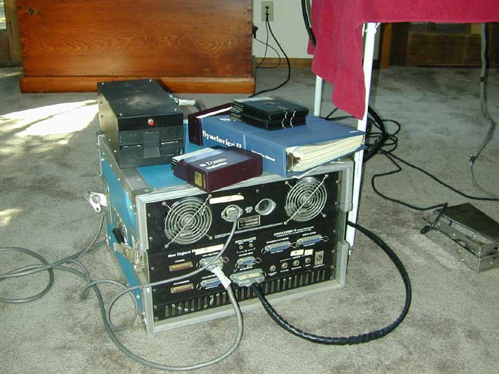
Synclavier:
digital 8-Bit FM/additive synthesizer, later 16-Bit sampling
and harddisk recording, subsystems (ABLE, FM, poly, ...) later
in separate "bins" in system rack
(see also Yamaha FM synthesizer section for comparison of FM technologies)
Sound
generator :
| FM/additive
voice |
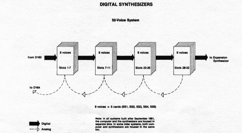
8-Bit
FM/additive voice is called "FM voice", 8 voices
= one FM generator card plus 4 controller cards (SS1-SS5
card-set), later optional Stereo upgrade: 8 Stereo voices
= two new FM generator cards plus 4 controller cards (and
new software), max. 32 FM voices per system, 1 carrier +
1 modulator oscillator per voice, 8-Bit phase and waveform,
pitch by variable clock and variable phase increment per
oscillator, digital phase adder (the "FM" is actually
implemented as a phase modulation, www.500sound.com: diagram),
variable carrier waveform (32 "timbre frames")
for additive synthesis, analog multiplying DACs for carrier
output envelope, sound can consist of up to 4 FM voices
("layers") in parallel (one FM voice then called
"partial timbre"), FM-voice also used for resynthesis
of samples |
| Sample-To-Disk |
("STD",
"ADX/DAX") 16-Bit monophonic sampling/sample-playback
option directly to/from IMI harddisk ("International
Memories Incorporated", ST506 MFM type), 1kHz-50kHz
(0.1kHz steps) mono |
| Sample-To-Memory |
("STM",
"Analogics") 16-Bit monophonic sampling option,
max. 50kHz stereo/100kHz mono |
| poly
(sampling) voice |
16-Bit
polyphonic sample-playback voice is called "poly (sampling)
voice", "PSV" (PS versions) and "DDV"
(DTD and later) cards, max. 100kHz sample rate, phase-locked
sample-playback, optionally Stereo and panning, separate
multiplying DACs per voice (2 if Stereo) with analog envelope,
ABLE Model C or D required, max. 32 poly voices per poly-bin,
shared "poly RAM" sample memory (missing in disk-recorder
versions), max. 32MB poly RAM (128MB with Model D) per poly-bin,
max. 3 poly-bins, sample input via STM |
| Multichannel
Distributor |
("MD")
output router |
ABLE: 16-Bit "single-instruction" system control
processor/minicomputer (proprietary non-microprocessor CPU), XPL
programming language (later called "Scientific XPL"),
Model A/B/C/D versions (poly voices since Model C) (www.cs.dartmouth.com:
info,
home.earthlink.net/~yaking: cards)
ABLE software:
RTP ("Real-Time Program", Synclavier real-time system)
SFM (sound editing environment)
Monitor (command line interpreter)
Screen Editor
("SED", text editor)
SCRIPT (music/score editing/printing language)
"Memory Recorder" (sequencer, 32/200 tracks)
Models: (more infos on home.earthlink.net/~yaking:
models,
cards)
prototype/research model (1975):
* Darmouth Digital Synthesizer (digital FM/additive synthesizer,
developed in 1975 at the Dartmouth
College/New Hampshire by Sydney Alonso/Jon Appleton/Cameron
Jones, ABLE processor)
early NED models (>=1976)
8-Bit FM voices, Model B or C ABLE
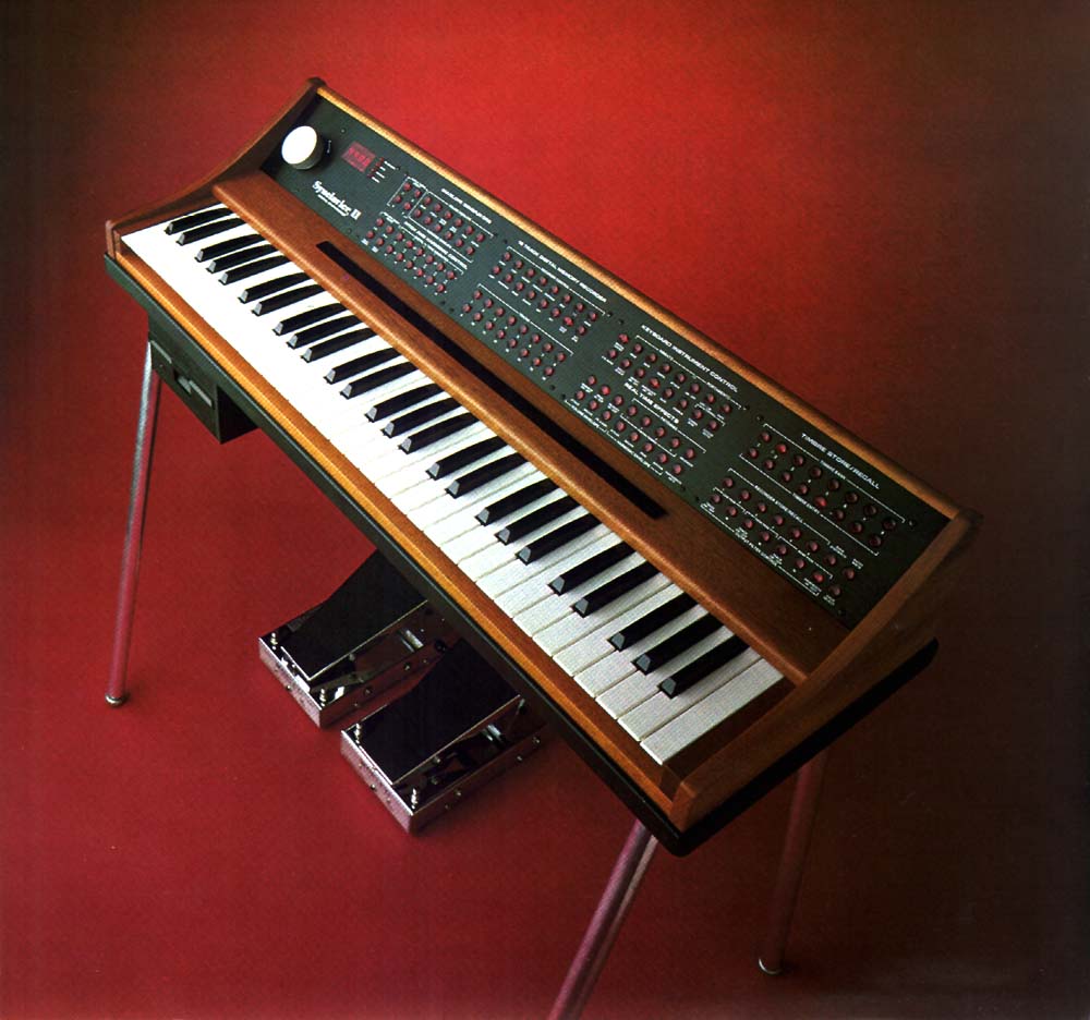
* Synclavier Digital Synth (1977)
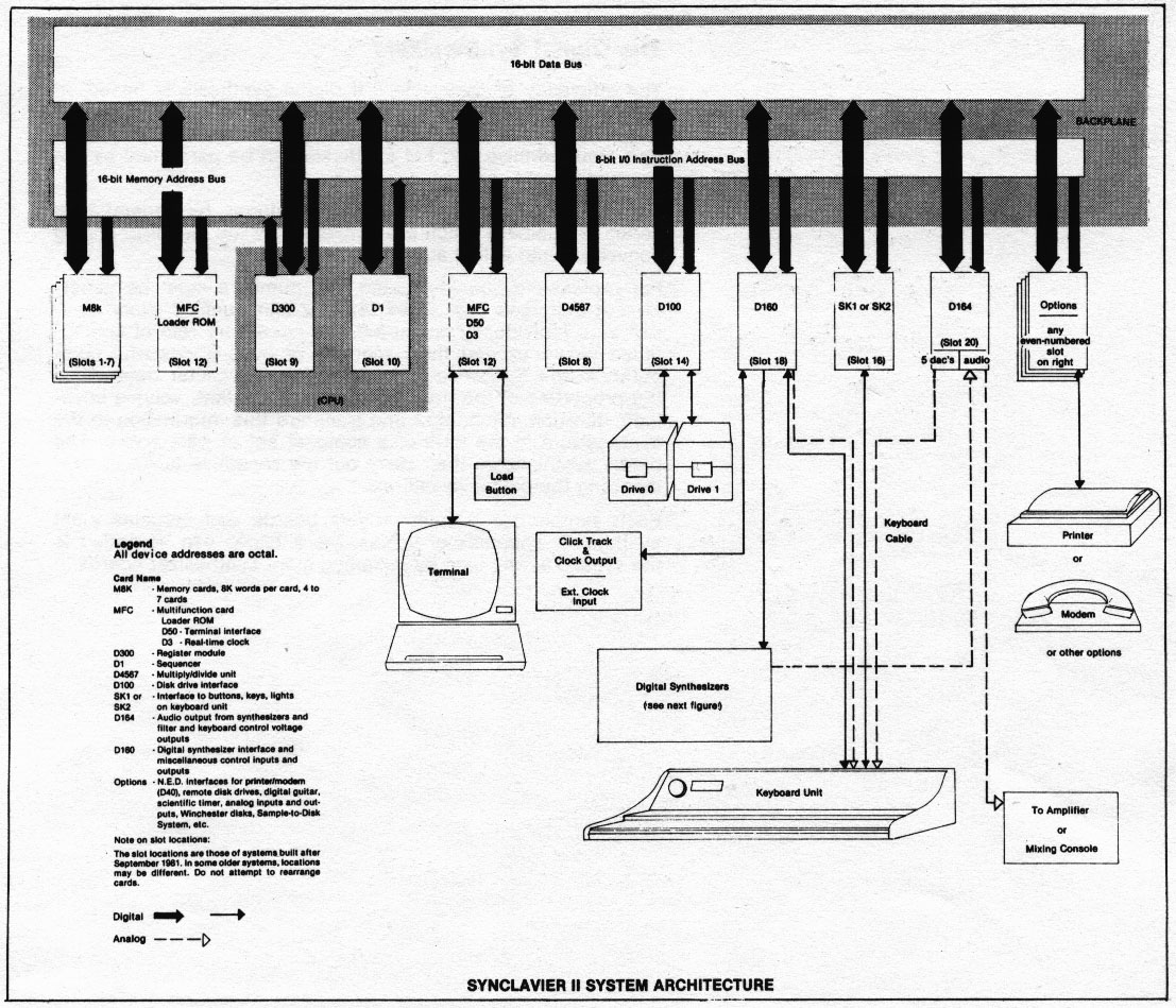
* Synclavier II (1980)
(links: to www.500sound.com: info,
control
architecture, synthesizer
architecture, synthesizer
schematics, main
unit, "ORK"
("Original Release Keyboard") keyboard, terminal)
Stereo FM option
MIDI option
Sampling option ("Sample-To-Disk", 1982)
IMI ("International Memories Incorporated", ST506 MFM
type) harddisk controller (later SCSI)
PS models ("Synclavier", 1984?):
"VPK" velocity sensitive keyboard, Model C or D ABLE,
PSV 16-Bit poly voices, 8-Bit FM voices, Digital VT640 terminal
(links: to www.500sound.com: picture)
* PSST (16-Bit sampler, small tower)
* PSMT (8-Bit FM/additive synthesizer + 16-Bit sampler, medium
tower)
* PST (8-Bit FM/additive synthesizer + 16-Bit sampler, large tower
with 3 poly-bins)
Harddisk recording (1986?):
Model C or D ABLE, DDV 16-Bit poly voices, no poly RAM (sample
playback directly from disk)
* DTD ("Direct-to-Disk", digital recording/editing,
option to Synclavier or stand-alone system, 16 tracks)
(links: to www.500sound.com: info,
specs, picture,
picture)
3200/6400/9600 models (>=1988?):
successors of PS series, Apple Macintosh as control console (instead
of the Digital VT terminal), Model D ABLE, DDV 16-Bit poly voices
(like in DTD), optional 8-Bit FM voices, Multichannel Distributor
("MD", output router)
* Synclavier 3200 (16-Bit sampler, 32 poly voices (Mono), 32MB
poly RAM, small tower)
(links:
to www.500sound.com: info+picture)
* Synclavier 6400 (like 3200 but Stereo, small tower)
* Synclavier 9600 (8-Bit FM/additive synthesizer + 16-Bit sampler,
32-96 poly voices, up to 768MB poly RAM, large tower)
(links: to www.500sound.com: info,
specs, info+picture)
Post-production packages:
* Synclavier TS ("Tapeless Studio", PSMT + DTD)
* PostPro (DTD standalone system + special console)
(links: to www.500sound.com: info+picture)
* PostPro SD ("Sound Design", integrated 6400 and DTD)
DEMAS & Synclavier Digital Corporation (>=1999):
ABLE subsystem (Model C or D) replaced by Apple PowerMac (PowerPC
CPU) as control computer with ported Synclavier software
(links: www.synclavier.com: DEMAS
info, www.earthlink/~yaking: info,
brochure)
- PODX
on PDP-11/23 + DMX-1000
DMX-1000: digital signal processor developed by Dean Wallraff
at Digital Music Systems (see: Computer Music Journal 3(4), 44-49
(1979))
POD/PODX: music software system by B. Truax (home,
POD+PODX infos),
first PODX version 1982 for PDP-11/23 + DMX-1000, since 1986 with
real-time granular synthesis (B.Truax: GSX
info)
- Yamaha
digital FM synthesizers:
Note: In contrast to the NED Synclavier (1 modulator + 1 carrier
per voice and variable carrier waveform), older Yamaha FM synthesizers
(GS/CE/DX series) use various stack-like configurations (called
"algorithms") with higher order stacks/trees of FM-modulating/modulated
sine-wave oscillators (called "operators").
(The content of this web site reflects the personal
opinion of the author, the information given is not guaranteed
to have anything in common with the products of Yamaha.
This web site is in no way affiliated with Yamaha. Please visit
their web site for information about their products. See
also disclaimer.)
links:
www.sospubs.co.uk:
info1,
info2,
Markus Fiedler: FM
(old
link)
www2.yamaha.co.jp: Yamaha
model history,
www.dxmuseum.com:
timeline,
www.dx7heaven.com
www.kratzer.at: DX1
Dave Benson:
DX7
www.keyboardmuseum.com:
Yamaha
digital FM prototype
see Markus Fiedler's infos
and pictures
GS1/GS2 (1981)
preset digital FM synthesizer, 16 voices, memory for 16 sounds,
later optional MIDI interface (GSMI-1/GSMI-2)
links: www.sospubs.co.uk: info1,
info2,
uni-regensburg.de: info
GS1: 8 operators per voice: 4 carriers with one modulator
each (crossmodulation between 2 modulators), 88-key velocity and
poly-pressure sensitive weighted keyboard (www.keyboardmuseum.com:
picture)
GS2: 4 operators per voice: 2 carriers with one modulator
each (crossmodulation between 2 modulators), 73-key velocity sensitive
weighted keyboard (www.keyboardmuseum.com: picture)
Overview:
The GS1 sound-generator is basically a "double-GS2"
system with enhanced control/modulation possibilities (random
detune modes and poly-pressure sensitive keyboard). Sounds were
supplied by Yamaha on magnetic cards (the GS1/GS2 are not user-programmable).
Each side of such a card contains sound data for 4 operators (thus,
the GS1 needs two "sides" of sound data for its 8 operators,
which can also be combined arbitrarily from different cards).
Compared with later DX-series models, the GS1/GS2 provide only
one "algorithm" (with
crossmodulation).
(Author's note: As for the offered features, the relationship
between the GS1 and GS2 models is comparable to that of the DX1
and DX7 synthesizers. The GS1/GS2 design can be considered as
the first LSI implementation of digital FM synthesis, building
the basis for the following VLSI generation of DX series synthesizers
and other "mass-market" FM-based keyboards by Yamaha.)
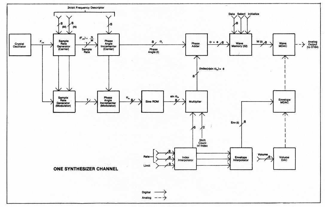
Principle:
The digital FM sound generator for 16 (mono-timbral) voices with
4 operators each (2 carriers with one modulator each, sine-waves)
is implememented as the "FM" module PCB. The "FM"
algorithm is actually implemented
as a phase-modulation. Each modulator provides its waveform output
as a modulation input to its carrier and also to the other modulator
(with selectable cross-modulation mode). The FM module contains
various proprietary LSI digital integrated circuits (5 per operator).
Each operator is shared in a cyclic 16-phase round-robin scheme
between its 16 mono-timbral channels with fixed sample output
rate (370kHz/16=23kHz). The FM module also contains the 10-Bit(+sign
Bit) audio output DAC (NEC uPD610D). The GS2 contains one FM module
(4 operators), whereas the GS1 contains two FM modules in parallel
(8 operators).
The "KC" keyboard-scanner/controller module controls
the FM module(s). It contains the master oscillator (at 3x370kHz)
which is modulated by a vibrato LFO (on A module, see below).
The KC modules also contains the key velocity controller ("inital
touch"). In the GS1, additional key-pressure sensors and
an additional "MPX" module decodes and generates poly-pressure
("after touch") control data, which is multiplexed with
the velocity control data to the FM module. Detune effects are
generated by use of dedicated detune/random/pitch control inputs
of each individual operator (note: only the GS1 makes use of the
random tune control inputs of the FM module). Optionally, key-code
data can be redirected through a separate key-event generator
module (e.g. a MIDI interface board).
The "RW" sound memory module contains a 8035 (ROM-less
8048 variant) microcontroller with 2KB firmware ROM and 2KB/4KB
sound SRAM for the GS2/GS1. It is connected to the voice registers
on the FM board (via drivers on the KC board) and various control
elements/switches. The sound SRAM (with battery-backup) contains
16 sounds (4x256Bits per sound with 4 operators). The card-reader
(Canon K-15913-93), which can load/save sounds to/from the SRAM,
is connected to this RW module. A programmer interface on the
RW board provides the possibility to load/save sound data to the
GS1/GS2 from an external programming device.
Audio signals from the FM module(s) are post-processed on the
"A" analog module, which contains an "ensemble"
effect engine based on analog BBD chips (3x MN3009) and a "tremolo"
effect circuit. Furthermore, the A module contains the LFOs for
the tremolo and vibrato modulation effects, which are controlled
by foot pedals and front panel elements. With the GS1, each FM
module has its own audio output, connected to two audio inputs
on the A module. The GS2 has the same A module, but here, both
audio inputs are connected to the same FM module output.
The GS1/GS2 has also a built-in three-band equalizer (on a PCB
located on the front-panel) which is connected to the A module
(between ensemble engine output and tremolo modulator input).
Algorithm block diagram:
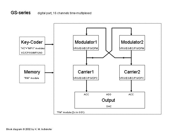
Integrated circuits (LSI):
KC (YM311) "Key Coder": 1x on KC board, key-switch
input from keyboard, key-code output to CP
CP (YM312) "Channel Processor": 1x on KC board, key-code
input from KC, enevelope state input from EC, control outputs
to IG/AG/MPX/VRG/EG/PG
IG (YM320) "Initial Touch Generator": 1x on KC board,
key-code data input from CP, initial touch (velocity) control
output to EC
MPX (YM318) "Multiplexer": 4x on MPX board, analog pressure
control input from keyboard, key-code data input from CP, multiplexed
pressure information to AG
AG (YM334) "After Touch Generator": 1x on MPX board,
multiplexed pressure information from MPXs, key-code data input
from CP, after touch (pressure) control data output to EC
VRG (YM347) "Voice Register": 4x on FM board, sound
data register, serial sound data input from RW board (via KC board),
key-code data input from CP (for scaling), current-state input
from EG, rate and level information output to EG, frequency control
output to PG
EG (YM321) "Envelope Generator": 4x on FM board, 4-state
envelope generator (attack, 1st decay, 2nd decay, release), rate
and level information input from VRG, key-code data input from
CP, current-state output to VRG, envelope output to EC
EC (YM322) "Envelope Controller": 4x on FM board, envelope
input from EG, modulation input from IG/AG/VRG, envelope output
to OPC/OPM, envelope state output to CP
PG (YM344) "Phase Generator": 4x on FM board, variable
phase accumulator, frequency control input from VRG and modulation
elements, phase output to OPC/OPM
OPC (YM34501) "Operator-Carrier": 2x on FM board, phase
adder + sine-ROM + envelope multiplier, phase input from PG/OPM,
waveform output to ACC
OPM (YM34502) "Operator-Modulator": 2x on FM board,
phase adder + sine-ROM + envelope multiplier, phase input from
PG/OPM, waveform output to OPC/OPM, selectable cross-modulation
mode input from VRG
ACC (YM316) "Accumulator": 2x on FM board, waveform
data accumulator for 16 channels, waveform input from OPC, serial
channel sum output to ADD
ADD (YM327) "Adder": 1x on FM board, serial channel
sum input from two ACCs, output to DAC
SECII (YM633) "Symphonic Ensemble Controller": BBD controller,
1x on A board
MIDI kits (1984):
GSMI-1
GSMI-2
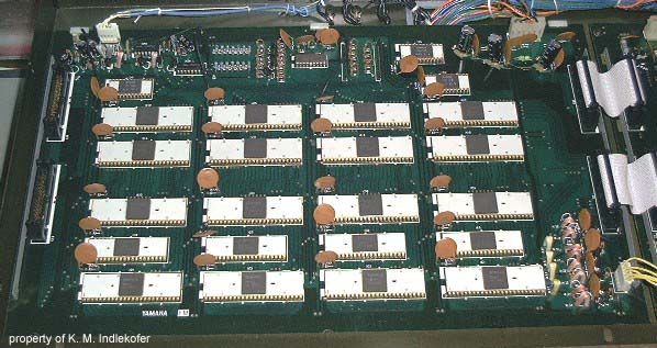
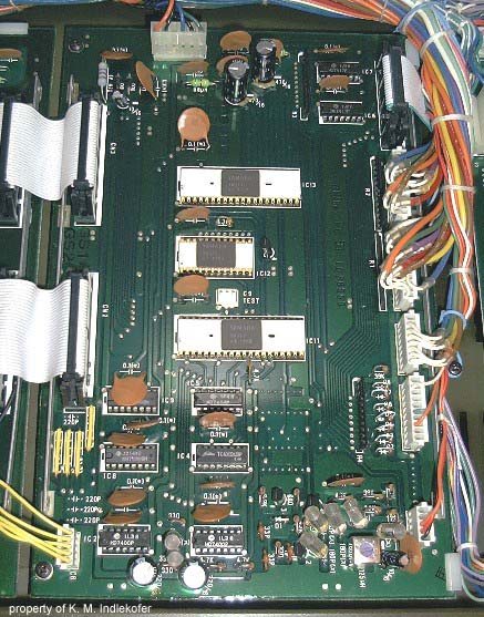
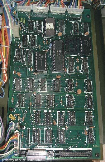
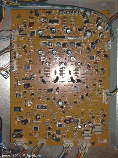
Pictures:
GS2:
- synthesizer (fully mounted)
- inside (A module to the left,
FM+KC+RW modules in black metal housing)
- FM module (1 per GS2 and 2 per
GS1, KC module to the right)
- KC module (FM module to the left,
RW module to the right)
- RW module (KC module to the left,
programmer connector empty)
- A module
- magnetic sound card (with write-protection
"edge")
CE20/CE25 (1982)
preset FM (home-)keyboard (www.keyboardmusem.com: info,
www.sospubs.co.uk: info)
DX7 (1983)
programmable digital FM synthesizer, 16 voices, 12-Bit, 28kHz,
6 operators/32 algorithms (Dave
Benson: MIDI + schematics, info,
info)
Principle:
The sound generator for 16 voices with 6 operators each is implemented
as two intergrated circuits (VLSI):
EGS (YM21290): digital envelope generators (pitch, amplitude),
LFO
OPS (YM21280): digital operator (phase accumulator, modulator,
adders, sine-ROM)
The operator output words (6 operators and 16 channels) are generated
sequentially by use of a round-robin scheme, running at 16x6x
the fixed sample output rate (with a 4-phase 9.42MHz/2 master
oscillator). The routing of operator output data within the OPS
chip in each round-robin time-slice is controlled by the selected
algorithm. Frequency information (i.e. phase increment) has a
resolution of 14 Bits, amplitude envelope data is 12 Bits. The
"FM" is actually implemented as a phase modulation,
i.e. a modulator operator output is added to the phase of the
carrier operator (behind the carrier's pitch phase accumulator)
and then fed into the sine-ROM. The sine-ROM output is scaled
by the amplitude envelope data and the result (i.e. the operator
output) is stored temporarily in a register. The OPS is followed
by a 12-Bit DAC (BA9221) with a 4-Bit binary attenuator.
The sound generator subsystem is controlled by a 63B03 CPU, whereas
a 6805 CPU is used as a keyboard scanner.
DX1 (1983)
basically a "double-DX7" with enhanced control and programming
possibilities (www.kratzer.at:
techinfo)
DX9 (1983)
programmable digital FM synthesizer, 16 voices, 4 operators/8
algorithms
TXn16 (n=1...8, 1984)
typically sold as TX216 and TX816
TF1: 16-voice module (DX7-like FM generator, 1-8 in frame)
MIDI RACK: MIDI multiplexer + power supply module
built into 19" rack-mountable frame for up to 8 TF1 modules
(links: www.keyboardmuseum.com: info,
info+manuals)
DX5 (1985)
successor of DX1 (www.keyboardmuseum.com: info)
TX7 (1985)
keyboard-less DX7 MIDI sound generator (www.keyboardmuseum.com:
info)
DX21 (1985)
successor of DX9, split- and layer-modes (www.keyboardmuseum.com:
info
DX27/DX100 (1985)
low-price variants of DX21, DX100 is mini-keyboard version of
DX27 (www.keyboardmuseum.com: info)
- E-MU
www.emu.com: timeline
See also the Emulator
Archive for many useful infos and links.
(The content of this web site reflects the personal
opinion of the author, the information given is not guaranteed
to have anything in common with the products of E-MU
or Digidesign or Apple.
This web site is in no way affiliated with them. Please visit
their web sites for information about their products. See
also disclaimer.)
Samplers:
Emulator I (1981, 1982 mark 2)
2/4/8 channels, mu-255 companded 8-Bit, 128KB RAM, Z80 CPU, "mark
2" with VCA analog post-processing
Links:
www.emulatorarchive.com: brochure,
manual,
info
Emulator II (1984, 1985 II+)
8 channels, DPCM mu-255 companded 8-Bit (i.e., the analog difference
between the new input sample and the accumulated DAC output of
the previous sample is converted via mu-255 to an 8-bit value),
512KB RAM (per bank), 2x Z80 CPUs (main and scanner), proprietary
74-TTL based processor (Emulator II "Microcontroller")
for shared 8-channel address calculation (with forward/backward
looping capabilities), pitch generation based on variable sample
output rate via separate frequency dividers (from a 10MHz master
clock) within the range of 12-66kHz with a rather poor resolution
of 2-10 cents, fixed sample input rate 27.7...kHz (=10MHz/360),
separate DAC (AM6072) and VCF/VCA analog post-processing (SSM2045)
per channel, sample input ADC based on channel0 DAC with SAR,
RS422 computer interface (shared with MIDI, used for control by
Apple Macintosh), proprietary floppy format (low-level as well
as filesystem layout, DS/DD 80 tracks with 0xE00 bytes per track
and side).
The Emulator II has a very unique sound quality due to its analog
post-processing, the DPCM mu-255 companding, and the divider-based
variable sample-rate principle. Sample editing can be accomplished
by use of the "SoundDesigner for the Emulator II" (legacy
software, originally by Digidesign)
running on an Apple Macintosh
computer (which can be attached to the RS422 interface).
Models:
* Emulator II: 1 RAM bank (512KB), 2 floppies
* Emulator II+: 2 RAM banks (512KB each)
* Emulator II+HD: 1 harddisk and 1 floppy
Links:
www.emulatorarchive.com: story,
brochure,
schematics
www.sonicstate.com: info
Jeff Bergman:
info
For later models (e.g. the Emulator III or Emax) please see the
Emulator
Archive.
- PPG
PPG ("Palm Products Germany", 1974-1987, Hamburg/Germany)
links:
Hermann
Seib's PPG page: infos
antarcticamedia
info,
machines.hyperreal.org:
history
info,
Till Kopper's
infos
wavetable synthesizers with analog post-processing:
(Hermann Seib: documentation/manuals):
Wave Computer 360 (1978)
A/B models: 4/8-voice, no VCFs
(www.antarcticamedia.com: info,
www.synthmuseum.com: info)
Wave 2 (1981)
8-Bit, 8 voices, 1 DCO per voice (variable sample rate), VCFs/VCAs
(www.synthmuseum.com: info)
Wave 2.2 (1982)
8-Bit, 8 voices, 2 DCOs per voice (phase accumulator with fixed sample
rate), 2-way multi-timbral, for use with Waveterm A
(Hermann Seib: MIDI-upgrade)
Waveterm A
waveform editor/sampling option, for Wave 2.2, 8-Bit, additive
synthesis/resynthesis, based on ELTEC Eurocom II V7 computer with
6809 CPU and FLEX9 OS, see mainpage for
more infos about FLEX 9
(Hermann Seib: info,
www.synthmuseum.com info)
Wave 2.3 (1984)
12-Bit, 8-way multi-timbral, MIDI, for use with Waveterm B
EVU ("Expansion Voice Unit", rackmount
Wave 2.3
(Hermann Seib: info,
, MIDI-upgrade,
www.synthmuseum.com: info)
Waveterm B (improved Waveterm, for Wave 2.3, 16-Bit,
6809+68000 CPU)
Wave 2.3 Principle:
Wavetable synthesizer with "drop/add" fixed sample output
rate and analog post-processing.
There is a total of 8 voices, each consisting of 2 digital oscillators,
which gives a total of 16 oscillators. Oscillator sample address
calculation is done via round-robin scheduling at a fixed sample
output rate. The total waveform RAM has 64K 12-Bit words, consisting
of 8 wavetables (in order to be multi-timbral), where a wavetable
consists of 64 partial waves of 128 samples each. (Note: Once
a new sound is selected, the corresponding wavetable is downloaded
into the waveform RAM from a large wavetable-EPROM or an external
Waveterm.) A phase accumulator at a fixed sample output rate with
pitch variation by variable phase increment per oscillator is
employed. The phase accumulator is implemented as a fixed-point
29-Bit register/adder with a 13-Bit fractional part and 16-Bit
integer part. In the integer part, the lower 7 Bits address the
sample within the current partial wave (128 samples) and the upper
9 Bits provide the partial wave number (8x64 partial waves). However,
the phase increment is only 15-Bits (13 fractional and 2 lower
integer Bits). Each oscillator has its own phase, partial wave
number and phase increment register (contained within multiple
74LS189 SRAMs) with a phase incrementer logic (implemented via
multiple 74LS283 adders and 74LS379 registers), shared among the
oscillators in a cyclic round-robin fashion. The current output
sample value is simply obtained by an add/drop sample output algorithm
(i.e., given by the waveform sample at the integer part of the
phase accumulator as the waveform RAM address). Waveform RAM and
processing is located on the "PROZ. Board", also called
the "Sound Computer". Each voice (2 oscillators) has
a separate DAC and a VCF/VCA analog post-processing section, located
on two "Voice Boards" "OF4" with 4 voices
each. The OF4 contains the four 12-Bit sample output DACs (4x
AD7545KN) and four VCFs with variable resonance (4x SSM2044) and
four VCAs (2x CEM3360). The "I/O Board" contains the
main controlling components, such as the 6809 CPU, main RAM, OS-
and wavetable-EPROMs, keyboard and panel interfaces, parts of
the MIDI interface and the control-voltage ADC (ZN427E-8) and
DACs (3x AD558). The three control-voltages (for the VCFs/VCAs
on the OF4) are demultiplexed (and sampled by following S/H amplifiers)
on the OF4 to four voices. The "PPG COM. BUS" is directly
connected to the "PROZ. Board".
Realizer (prototype, sampler/wavetable/FM/analog
model digital synthesizer, 8x TI TMS32010 DSPs, 1x Motorola 68020
CPU, 4MB RAM, 12x 16-Bit DACs, 2x 16-Bit ADCs, SCSI, AES/EBU,
44.1kHz, 1986)
(www.antarcticamedia.com: info,
www.synthmuseum.com: info)
sucessors: see Waldorf:
Microwave, Wave
- Waldorf
Microwave (1989)
rack-mount wavetable synthesizer with digital sound generator ASIC, MP7545 DACs,
and analog VCF/VCA post-processing (Rev A: CEM3389, Rev B: CEM3387), 68000 host CPU,
based on the PPG Wave 2.2 synthesizer
Till Kopper: Microwave
www.unofficial.waldorf-wave.de: Wave
- Akai
samplers:
www.vintagesynth.org: info,
www.cs.uu.nl: info,
www.obsolete.com: history
S612 (12-Bit, 128KB, 6 voices, max. 32kHz sampling, 1985, www.vintagesynth.org:
info+manual)
S700 (12-Bit, 6 voices)
S900 (12-Bit, 750KB, 8 voices, 7.5-40kHz sampling, 1986, www.vintagesynth.org:
info)
S950 (750KB-2.25MB, 7.5-48kHz sampling)
S1000 (16-Bit, 2-32MB, 8 voices, 44.1/22.05 kHz sampling, 1988,
www.vintagesynth.org: info+manual)
S1100 (16 voices, 1990)
- Ensoniq
(www.klangmaschine.com:
infos, www.emu.com: timeline)
samplers:
Mirage DSK-8 (1984, 8-Bit, 144KB, 10-33kHz, VCA+VCF, Chips: "Q-Chip",
6809, Electric
Enver: infos)
Mirage DSM-8 (1985, rack version)
Mirage DSK-1 (1987)
EPS (1988, 16-Bit (13-Bit ADC/DAC), 2MB, 6.25-52kHz, Chips: "OTTO",
"ESP")
EPS 16 Plus (1990, 16-Bit, 2MB, 11.2-44.6kHz, Chips: "OTTO",
"ESP")
ASR-10 (1992, 16MB, stereo sampling, Chips: "OTTOR2",
"ESP", 68302)
ASR-10R (1993, rack version)
ASR-88 (1995)
ASR-X (1997, Chips: "OTTOR2"?, "ESP2")
synthesizers:
ESQ-1 (1986, VCA + VCF, Chips: "Q-Chip")
ESQ-M (1987, rack version)
SQ-80 (1988, Chips: "Q-Chip")
VFX, VFX-SD (1989, Chips: "OTTO", "ESP")
SQ-1, SQ-R (1990)
SQ-1 Plus (1991)
SQ-2 (1991)
SD-1 (1991, Chips: "OTTOR2")
KS-32 (1992)
TS-10, TS-12 (1993)
KT-76, KT-88 (1994)
MR (1995, rack version, Chips: "OTTOR2"?, "ESP2")
MR-61, MR-76 (1996)
ZR-76 (1997)
Chips:
"SID" MOS6581: "Sound Interface Device" soundchip
(by Bob Yannes, not Ensoniq at that time) for Commodore C64, DCO/DCF/DCA
design
"Q-Chip" "DOC-I" ES-5503: "Digital Oscillator
Chip", 32 oscillators, 8-Bit
"DOC-II" ???
"OTTO" "DOC-III" ES-5505: 32 oscillators,
16-Bit
"OTTOR2" "DOC-IV" ES-5506: 32 oscillators,
16-Bit
"ESP" ES-5510: "Ensoniq Signal Processor",
DSP, 24-Bit
"ESP-2" ES-55??: DSP, 24-Bit
"OTTOFX" ES-5540: integrated OTTO+ESP
"OPUS" ES-5530: multimedia soundchip
"SGLU" ES-5701: system glue logic chip
Note: DOC wavetable playback chip is based on phase-accumulator
principle running at fixed sample output rate with round-robin
timesharing among voices
Download:
ASR-10/EPS-16Plus file system manager and WAV-to-INST converter:
asr10 (Rev.1.0) source,
binary
Please see disclaimer for
downloads !
Also try this to find more
software on the KMI site.
- KMI:
32-Bit floating-point Spectral Morphing Synthesizer (SHARC/MIPS
based, 12-voice DSP-board prototype: 1/2001 version 209.5.3)
based on a fixed sample output rate design with various interpolation
schemes
|
| |
|
| |
Analog
and Hybrid synthesizers: |
| |
|
| |
|
| |
Drum
machines: |
| |
- Linn:
LM-1
(www.synthmuseum.com: LM-1)
LinnDrum
(links: www.synthmuseum.com: picture,
www.machines.hyperreal.org: samples,
Forat: service
manual, Forat MIDI Mod)
8-Bit mu-255 companded waveform data format, pitch by variable
sample output rate (controlled by VCOs, VCFs/VCAs for post-processing)),
Z80A CPU, 8KB ROM, 8KB RAM,
sound generators based on VCO+counter+ROM+DAC(+VCF+VCA)
3 separate sound-generator systems:
a) TOM/CGA
b) SNARE/SSTK
c) TAMB/CABASA/CLAP/COWBELL/BASS/HI-HAT/RIDE/CRASH
Z80 address-space (periodic in 4000, except Forat MIDI
Mod blocks):
0000-1F7F: ROM (8KB)
1F80-1FBF: INPORT (read, input ports), STROBE (write, see below)
1FC0-1FFF: KEYBD (read, keys)
2000-3FFF: RAM (8KB, battery-buffered)
4000-5F7F: (Forat MIDI Mod)
8000-9F7F: (Forat MIDI Mod)
C000-DF7F:
(Forat MIDI Mod)
STROBE addresses:
1F80: 2-digit LED display (PATTERN#)
1F81: 2-digit LED display (STEP#/%MEM)
1F82:
LEDs
1F83:
LEDs
1F84:
LEDs, BEEP, output ports (TAPE SYNC, TRIGGER, CASSETTE)
1F85:
BASS
1F86:
SNARE/SSTK
1F87:
HI-HAT
1F88:
TOM/CGA
1F89:
RIDE
1F8A:
CRASH
1F8B:
CABASA
1F8C:
TAMB
1F8D:
COWBELL
1F8E:
CLAP
1F8F:
CLICK
Linn 9000
www.synthmuseum.com: Linn
9000
Forat9000 (based on Linn 9000) by Forat
Forat: Forat9000
- Akai
www.retrosynth.com: MPC-60
- Roland
CR78
TR808 (machines.hyperreal.org: samples,
schematics)
TR909 (machines.hyperreal.org: samples)
- E-MU
(Emulator
Archive)
Drumulator (8-Bit, 64KB waveform memory, shared DAC, 1983, www.emulatorarchive.com:
info)
SP-12
www.sonicstate.com: SP-12
(12-Bit @26.667kHz)
SP-1200
www.sonicstate.com: SP-1200
- Oberheim
DMX
- Simmons
machines.hyperreal.com: info
|
| |
|
| |
Effect
engines: |
| |
|
| |
|
|
|